Convert OBC Backlight
To LEDs
(and hopefully never
change them again)
Original instructions by
Michiel van Wessem with revisions and diagrams by Kent Williams.
 The
E30 on-board computer (OBC) has an orange-tinted LCD display that is illuminated
from the back by little incandescent bulbs. When these little fireflies
die, you're supposed to replace the light assembly. It's a nuisance because
it's a pain to get to the light assembly, and it's also rather costly --
as much as $30 for the assembly. The
E30 on-board computer (OBC) has an orange-tinted LCD display that is illuminated
from the back by little incandescent bulbs. When these little fireflies
die, you're supposed to replace the light assembly. It's a nuisance because
it's a pain to get to the light assembly, and it's also rather costly --
as much as $30 for the assembly.
These instructions will show
you how to substitute LED's for the standard 6-volt bulbs. LED's (light
emitting diodes) are durable. Their exact life span is still unknown, but
is thought to be at least 100 years.
This solution works excellently.
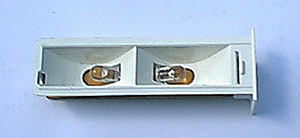
At the top of this page, you can see a photo of the finished light assembly
with LEDs. Since Gustavo Melo has very thorough instructions for
removing this light module in a separate forum article, that aspect of
the project is not covered here. This assumes that you have already
removed the module from the OBC.
Note: this procedure is
only suitable for people with good electronic soldering skills. Component
leads are cut short and soldering will have to be done very fast to avoid
overheating the components. You'll definitely need a low wattage
soldering pen.
Two LEDs and a resistor are
put in series. The LEDs are super bright orange (620 nm) LEDs with a 45º
viewing angle. I bought a pair from Mouser
Electronics for 50 cents each (plus shipping). You might want
to order an extra one or two just in case you break off one of the leads.
Mouser stock # is 512-MV8742. The resistor is 390 Ohm, 1/2 Watt and five
of them (that's the way they're packaged) at Radio Shack costs 79 cents.
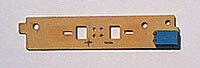 This
is what the little PCB looks like after you unhook the white plastic piece
and you de-solder the bulbs on the bottom of the board. You
can discard the incandescent bulbs and their little white holders;
you won't reuse these. With a pen I marked where the positive and
negative (ground) connections are on the board. Make sure to connect the
LEDs with the right polarity -- they are diodes. You can kill them if you
reverse them. The anode is the lead that is supposed to get the positive
voltage. One way to recognize the anode is that the lead is a little longer.
The name of the other lead is cathode. Another way to tell anode and cathode
is to hold the LED with its legs down and you look at the insides;
the anode ducks under the cathode. (See the figure below for clarification) This
is what the little PCB looks like after you unhook the white plastic piece
and you de-solder the bulbs on the bottom of the board. You
can discard the incandescent bulbs and their little white holders;
you won't reuse these. With a pen I marked where the positive and
negative (ground) connections are on the board. Make sure to connect the
LEDs with the right polarity -- they are diodes. You can kill them if you
reverse them. The anode is the lead that is supposed to get the positive
voltage. One way to recognize the anode is that the lead is a little longer.
The name of the other lead is cathode. Another way to tell anode and cathode
is to hold the LED with its legs down and you look at the insides;
the anode ducks under the cathode. (See the figure below for clarification)
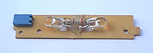 Now,
you stick the anode of one LED through the hole that is marked + on the
PCB board and solder it on the other side. The cathode of that LED is trimmed
short (about 3/8" to1/2" long). With the other LED, you stick the cathode
through the hole that is marked -, solder it there and trim the anode short.
Move the LEDs so that they stick up at about 15º. Now, take the resistor
and fold the leads back in sort of a loop. Cut them about a quarter inch
from each other, so they won't be able to touch. Now, solder the resistor
between the short cathode from one LED that is sticking out and the anode
of the other LED. You'll have to solder this one fast, or things will overheat
and die. You need to tuck the resistor in close to the anode and
cathode legs that are soldered to the board. The resistor will almost
be touching these leads. If you don't position the resistor in this
way, you'll have a hard time fitting the plastic reflector/cover over the
LED's. It's kind of a tight fit. See the diagram below for
more detail. Now,
you stick the anode of one LED through the hole that is marked + on the
PCB board and solder it on the other side. The cathode of that LED is trimmed
short (about 3/8" to1/2" long). With the other LED, you stick the cathode
through the hole that is marked -, solder it there and trim the anode short.
Move the LEDs so that they stick up at about 15º. Now, take the resistor
and fold the leads back in sort of a loop. Cut them about a quarter inch
from each other, so they won't be able to touch. Now, solder the resistor
between the short cathode from one LED that is sticking out and the anode
of the other LED. You'll have to solder this one fast, or things will overheat
and die. You need to tuck the resistor in close to the anode and
cathode legs that are soldered to the board. The resistor will almost
be touching these leads. If you don't position the resistor in this
way, you'll have a hard time fitting the plastic reflector/cover over the
LED's. It's kind of a tight fit. See the diagram below for
more detail.
 A blob of hot glue should be
added for a little more structural strength and to make sure that the wire
leads do not accidentally come into contact with each other. You
should probably try fitting the white reflector on before applying the
glue, just in case you have to do some last-minute tweaking on the position
of the LEDs and resistor.
A blob of hot glue should be
added for a little more structural strength and to make sure that the wire
leads do not accidentally come into contact with each other. You
should probably try fitting the white reflector on before applying the
glue, just in case you have to do some last-minute tweaking on the position
of the LEDs and resistor.
Now you can clip the white
plastic reflector plastic back on, stick the light assembly back in the
OBC, turn the ignition key on and behold! You should never have to
change the backlight again.
An additional benefit is that the
LEDs use less power then the incandescent originals... about 225
mW for the LEDs versus about 680 mW for the fireflies. Because
of this, you'll have less alternator drag so more fuel efficiency
and more power! :)
|